
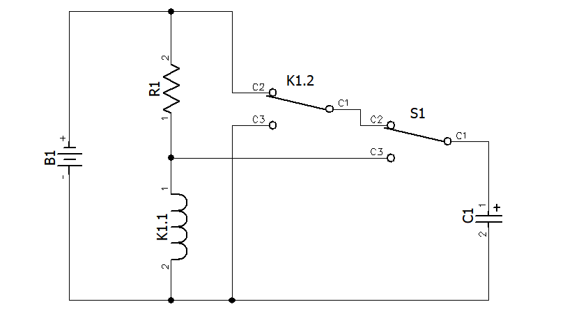
In one of my books this handy circuit for latching and un-latching a relay looked intriguing, so I tested it on the bench to verify its function. The resistor provides a holding current for the relay, but not enough to pull it in. In the off state, the capacitor is charged through the relay contacts and the NC contact of the momentary switch. When the switch is pressed, the charge on the capacitor is dumped across the relay coil, pulling it in. Once pulled in, the current through the resistor is enough to hold the relay on.
With the relay contacts in the opposite state, the capacitor is discharged through the momentary switch. When the switch is pressed again, the capacitor presents an initial short across the relay coil, de-energizing it.
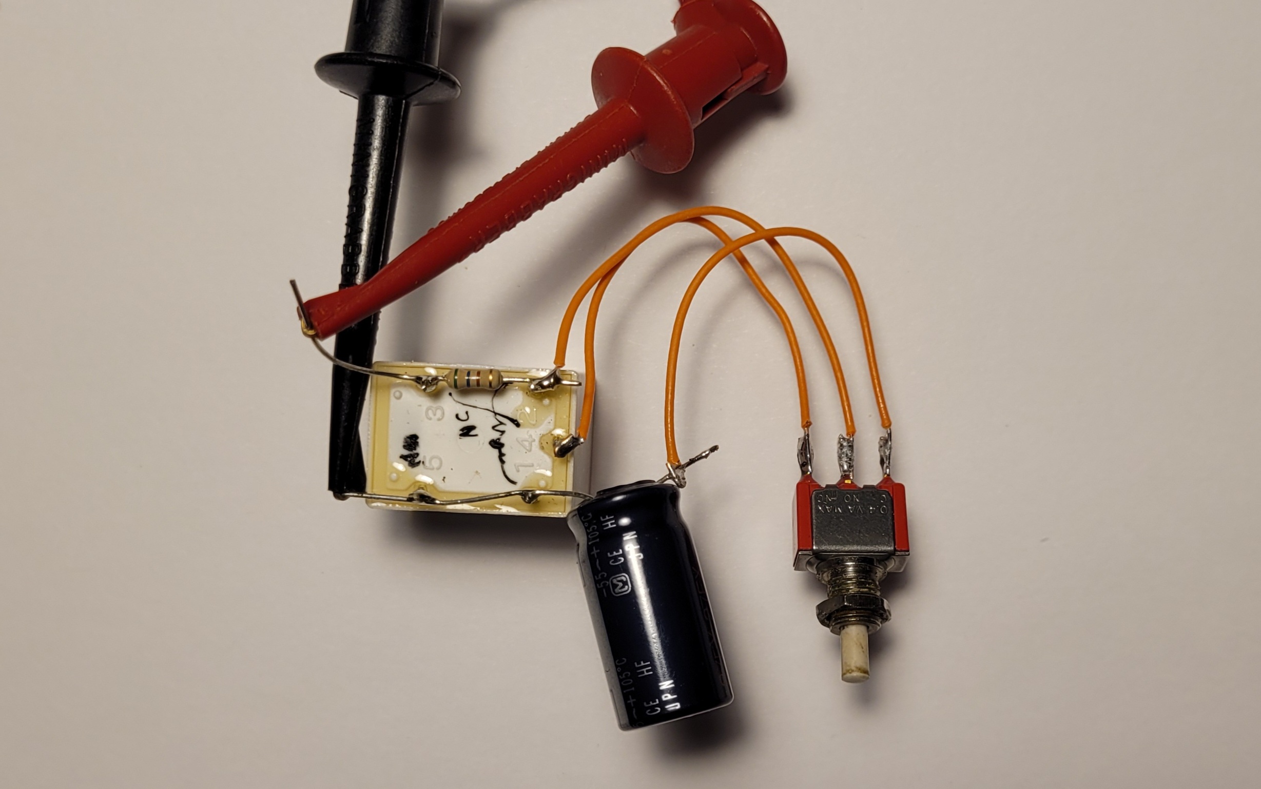
My version
I used a junk-box 12 V SPDT relay. Pull-in was around 8 V and drop-out around 3 V, with a measured coil resistance of 400 Ω. I chose 5 V as a good idle level for the coil and picked a 560 Ω resistor. Since the original circuit didn’t indicate values, I tried a 330 µF capacitor. I kludged it together on the bench, applied 12 V, and it performed as the article intended: press the switch to latch the relay, press again to un-latch it.
A small-value resistor can be placed between C1 of K1 and C2 of S1 to slow the charge/discharge current and prevent arcing.
The nice thing about this circuit is that if power is lost, it drops out and will not re-enable when power is restored — ideal for a power on/off application.