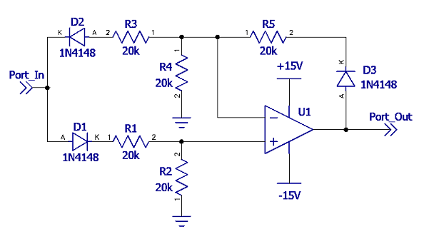
Figure 1 - Single Opamp Absolute Value Circuit
Single Opamp absolute value circuit
Figure 1 - Single Opamp Absolute Value Circuit
There are numerous circuits available that can perform an absolute value function using an op-amp. Many textbook examples start with a single opamp half wave circuit and simply add another opamp to make a full wave absolute value version. Among the various books I have, only one in my collection has the circuit shown here. This was originally published in Electronics magazine 1 in 1969 and I have not come across it in other books on opamp theory. The basic operation is fairly simple, during the positive half cycle D1 conducts and presents a voltage on the non-inverting input of the input voltage minus the voltage drop from D1 divided by two. Since D2 is cut off, the opamp is a standard non-inverting configuration with a gain of two. During the negative half cycle, D1 is cut off, which effectively puts the non-inverting input at zero volts via R2. Since the inverting input is also at zero volts, the opamp is now an inverting configuration with the input one diode voltage drop lower. Notice R4 has zero volts and therefore zero current, which effectively makes it transparent in this configuration. In both half cycles, since D3 is in the feedback loop, it compensates for the drops across D1 and D2. In my measurement of this circuit, the output can be loaded without affecting the operation. The measurement shown used a 4V pkpk sine at 1kHz input and the IC was a general purpose LM2904 operating from +/-15V.
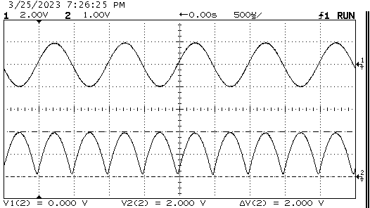
Figure 2 - Test Results
1 Spani, Wayne. "Absolute Value Circuit Needs Only One Opamp" Electronics Magazine, 20 Jan. 1969, pp. 87