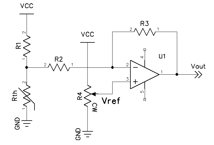
Figure 1 - Thermistor Linearizer
Thermistor Linearizer
There are many methods for linearizing an NTC thermistor and scaling the result for input to an ADC. Here is a practical circuit that linearizes the thermistor temperature curve and produces an output which is proportional to the temperature in volts. The voltage output allows it to be measured with a DMM or any voltage input data logger.
Figure 1 - Thermistor Linearizer
The linearization circuit is given in Figure 1. The circuit consists of a voltage divider which includes the thermistor and an inverting opamp with the non-inverting input set to a fixed reference voltage. The analysis of the circuit is as follows:
Since the opamp non-inverting input is at a reference voltage, the typical gain formula will not suffice. It is necessary to derive the overall gain using superposition. Setting the non-inverting input at zero volts, the gain is simply R3/R2. Shorting the input resistor R2 to ground and applying a source at the non-inverting input yields the non-inverting gain 1+(R3/R2). Combining the two yields the overall gain with a given Vref.
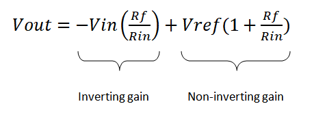
Figure 2 - Vout equation
To find the input voltage it is necessary to find the Thevenin equivalent voltage and input resistance. First the voltage divider R1/Rth is calculated. Next the parallel value of R1 and Rth are found and added to the input resistance R2. We now have V-thevenin and R-thevenin.
Since the endpoint thermistor resistance is used to find the range of the circuit, the unknowns are the feedback resistor R3 and Vref. Since we have R-thevenin and the gain is determined by R4/R-thevenin we can let G = R4/R-thevenin and solve for G in terms of Vin, Vout and Vref, yielding the following:
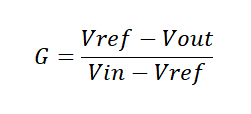
Figure 3 - Gain function
We now have two values for G, one at the lower and one at the upper temp, G-low and G-high. Using Excel solver, we find a minimum difference between G-low and G-high while adjusting Vref and targeting an equal R3 value for low and high. When a solution is found, the temperatures coorelate well to the output voltage. The best fit will be for narrow ranges as opposed to wider ones. Also, picking a thermistor that is optimal for the range will yield acceptable results.
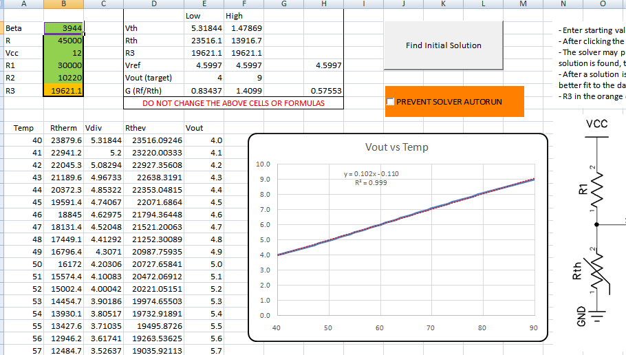
Figure 4 - Excel Spreadsheet
To use the spreadsheet, be sure to have the solver add-in installed in the analysis toolpak. Simply enter the thermistor data (beta and 25 deg resistance) in the green cells, enter the supply voltage of at least 2 volts above the maximum Vout and input starting values for R1 and R2. A good starting R1 value is 200k or at least 3x the highest thermistor resistance at the lowest temperature. A good value for R2 is 10k. After analysis these values and R3 can be tweaked to the closest one percent values and checked. A few iterations will yield an acceptable result. If solver does not find a solution, adjust R1 and R2 and retry, or if a solution is found they can be adjusted to minimize error over the range. If errors are encountered with using solver, it can be run manally by checking the prevent solver autorun
checkbox. The solver inputs are given below for manual entry.
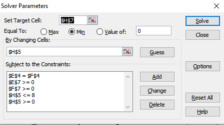
Figure 5 - Solver Settings
NOTE: I cannot claim the spreadsheet is perfected in any way. There are cases where no solution can be found. If you find improvements, please let me know and I can make updates to improve the tool.
Thermistor Linearization Spreadsheet for this example circuit