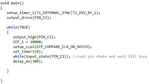
Figure 1 - C code for setting timer
Higher precision PIC Timer
The basis for this project was to define a precision 1 second gate for my reciprocal frequency counter
The timer modules in PICs and other microcontrollers are useful for most applications however they are not true hardware timers in the sense that they are not edge aligned to start on a rising or falling edge unless they have a gating or enable feature and cannot be synchronized to align to a clock edge to stop for generating a precise period. A recent project required a precise one second pulse which was to be derived from a precise 10kHz clock source which was supplied the the CCP module timer. Code was written to initialize the timer to zero, clear the CCP pin and when the preset count of 10000 was reached the CCP pin would clear, generating a one second pulse. The results were variable being greater or less than one second by enough margin to be unacceptable in the application. This variation in the period was exacerbated with the PIC running on the internal oscillator in which the frequency varied over temperature.
Figure 1 - C code for setting timer
Connecting a SN74LVC1G374DCKR D-flip flop with the clock source on the clock pin and the CCP output on D resulted in a precise one second pulse. There are a few instruction clocks between setting CCP pin high, preloading and intializing the timer and the point at which the timer begins to clock. When CCP does go high the D flip-flop Q output will follow CCP on the next positive edge of the clock source. When the timer gets to the compare value there are instruction clocks needed to clear the CCP pin. The D flip Q output then clears on the next clock rising edge. The flip flop syncs the CCP output to the clock edges and allows a precise period based on the timer count.

Figure 2 - D-flip-flop connection
This feature also worked on the delay instruction as evidenced by the exact 300ms pulse width. As long as the clock is an order of magnitude less than the instruction clock this method works well. I had no problem varying the clock from hundreds of Hz to 200kHz and also varying the preset count and in all cases the width was precise.
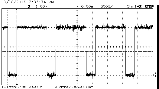
Figure 3 - Scope measurement of timer
The frequency counter and the function generator used as the clock source were both locked to my GPS disciplined 10MHz reference source for this experiment. Changing which pulse period is high or low is a matter of using the Q not output or by changing the C code from CCP_COMPARE_CLR_ON_MATCH to CCP_COMPARE_SET_ON_MATCH and changing the intial pin state prior to counting.
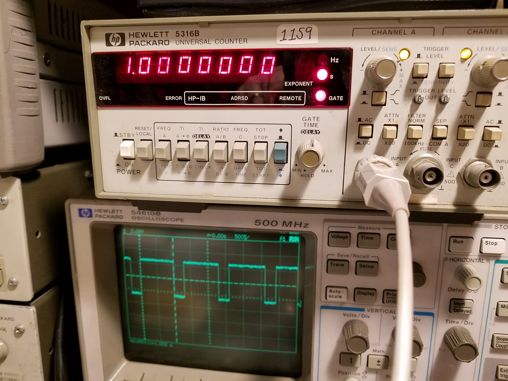
Figure 4 - Counter time interval measurement