
Orners Corner
Ham Radio • Electronics • Analog Design
Ham Radio • Electronics • Analog Design
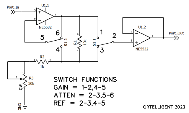
A flexible analog utility circuit providing selectable gain, unity reference, and attenuation using a modified non-inverting op-amp topology and a simple 3-position switch arrangement.
A practical analog signal level management circuit
While verifying the dynamic range of an audio compressor project, I needed a convenient way to rapidly switch between +10 dBu, 0 dBu, and -10 dBu reference levels without constantly adjusting the signal generator.
The goal was to establish a fixed reference level and then instantly move above or below that reference by precise amounts. Although originally developed for audio testing, the circuit has many additional applications in signal conditioning, instrumentation, and interfacing between consumer and professional audio equipment.
The circuit can easily be adapted for:
Voltage dividers and non-inverting amplifier behavior
The basic form of a resistive voltage divider follows the equation below:
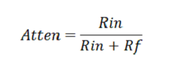
Resistive Divider Equation
Referring to the non-inverting amplifier configuration, we can see that this same divider network appears between the op-amp output and the inverting input as part of the negative feedback system.
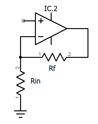
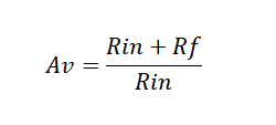
Therefore the gain equation of the non-inverting amplifier becomes the inverse of the resistive divider equation.
Three operating modes from one simple topology
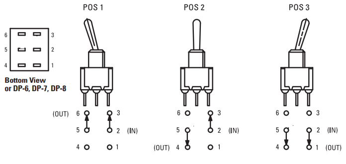
A slight modification of the standard non-inverting op-amp by adding a 3-way switch into the feedback loop provides three separate operating modes from a single circuit.
Implementation considerations and possible extensions
Because the circuit is non-inverting, the minimum gain will always be greater than or equal to unity.
The potentiometer can easily be replaced with a rotary switch using fixed precision resistors for repeatable preset gain and attenuation settings.
The switch shown in the example is an E-SWITCH 100DP6T1B1M2QE, although equivalent switches are available in several different form factors.
This circuit is intended as a flexible building block that can be adapted into many other analog signal processing applications.